On the (In)Security of 4G - Part IV: User and Control Plane, Bearer and the Protocol Stack
Table of Contents
4G User Plane
After learning about the different entities and their functionalities, let’s take a closer look at the user plane of 4G, starting with Evolved Packet System (EPS) Bearer Services.
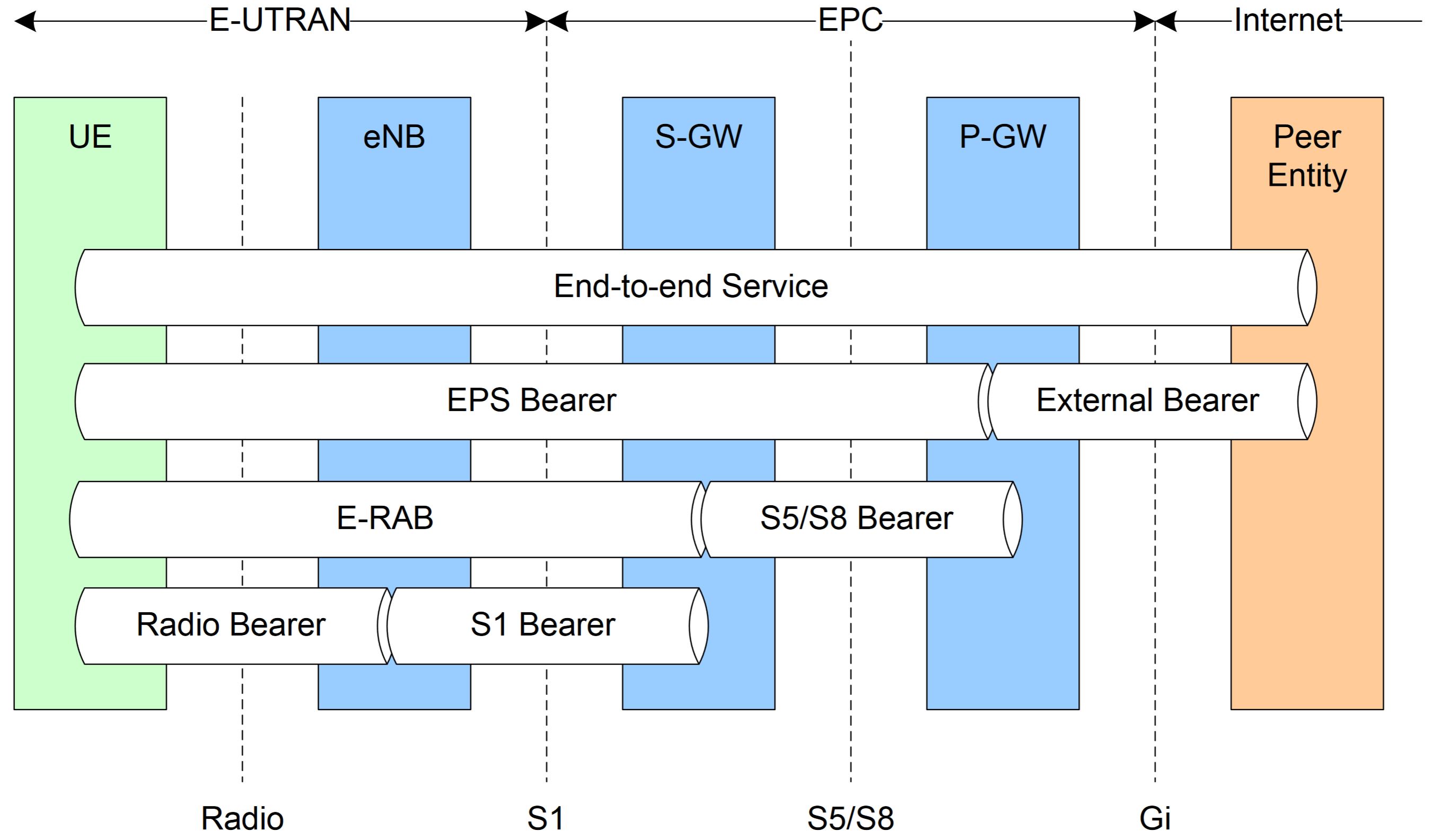
EPS Bearer Service Architecture
User plane data flow works by everyone connected to Long Term Evolution (LTE) having one or more EPS Bearer just for their traffic. User data flows from the UE –> eNB –> SGW –> EPC –> PDN GW –> PDN, which is depicted in figure 3 below.
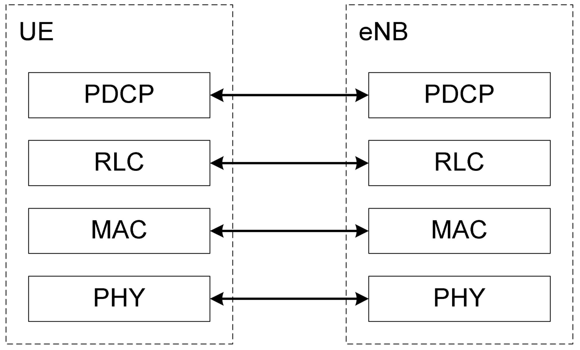
4G User Plane Protocol Stack
Communication of LTE data on the user plane between UE and the eNB happens on the following layers:
- Packet Data Convergence Protocol (RDCP) specified in 36.323
- Ciphering
- Integrity protection for C-plane
- In-sequence delivery and retransmission of PDCP SDUs for AM Radio Bearers at handover
- Duplicate detection
- Header compression using the Robust Header Compression (RoHC) protocol for U-plane
- Radio Link Control (RLC) specified in 36.322
- Error Correction through Automatic Repeat Request (ARQ)
- (re)-Segmentation
- Concatenation of Service Data Units (SDUs) for the same radio bearer
- In-sequence delivery
- Media Access Control (MAC) specified in 36.321
- Multiplexing/demultiplexing of RLC Packet Data Units (PDUs)
- Scheduling Information reporting
- Error correction through Hybrid Automatic Repeat Request (HARQ)
- Logical Channel Prioritization
- Physical layer (PHY)
A good overview of the entire protocol stacks an also be found on this page.
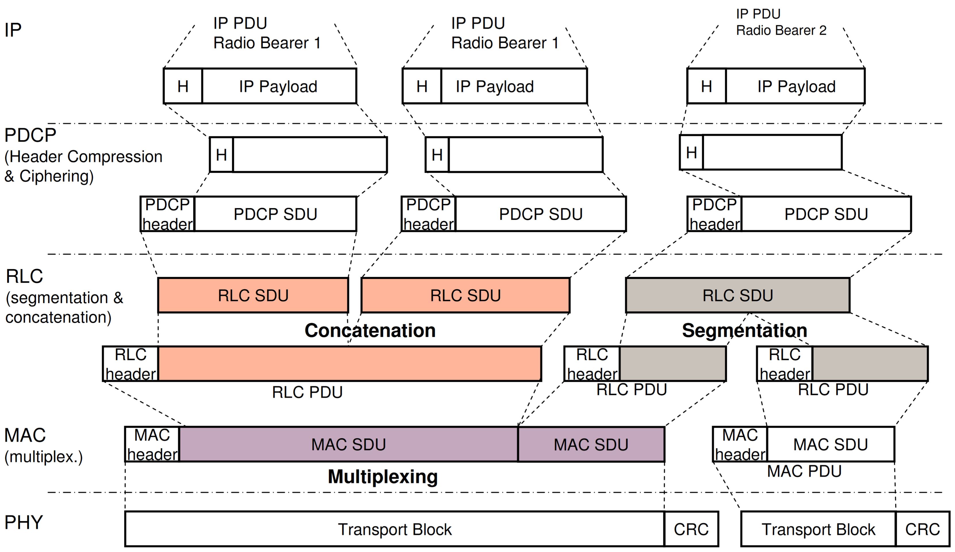
4G User Plane data flow
In figure 5, we see the data flow of user plane data from IP to PHY layer.
One IP Packet Data Unit (PDU) is assigned to one radio bearer, parsed onto the PDCP, where header conversion and compression to the PDCP header happens and ciphering takes place so that the previous payload is now turned into PDCP Service Data Unit (SDU). On the RLC this packet is put (PDCP header and payload together) in a RLC SDU and concatenated with packets for the same radio bearer, forming a RLC PDU with its own RLC header. Depending on the load of the link and the size of the MAC SDUs and finally PHY layer transport blocks, data can also be segmented from one RLC SDU to several RLC PDUS, optimally fitting the transport blocks and thus reducing header overheads on the PHY layer.
4G User Plane Scheduling
In general user plane scheduling is residing in the eNB as base stations of the LTE system. Here are some important information on the general scheduling ideas of LTE:
- Input - QoS parameters for EPS-bearers
- QoS Class Identifier (QCI) – per bearer (identifying particular service or classes of service)
- Guaranteed Bit Rate (GBR), Prioritized Bit Rate (PBR) – per bearer (accept/modify/drop bearers in case of resource limitation)
- Allocation and Retention Policy (ARP) – per bearer
- Aggregate Maximum Bit Rate (AMBR) – per group of bearers
- Aggregate maximum bit rate per group of bearers of a single user, Only for non-GBR bearers
- Scheduler residing in eNB
- Fulfilling above “QoS Contracts“,
- Maximizing cell throughput
- Providing Fairness
- Scheduling Information from UE
- Channel Quality Indication
- Buffer Status Report
- Power Headroom Report
- Uplink Sounding
- Scheduling for uplink: Logical channel prioritization and avoiding starvation
However, how is scheduling communicated and which control channels play an important role here? The following has some answers:
- Scheduling decisions dynamically signaled on L1L2 control channel Physical Dedicated Control Channel (PDCCH)
- 1ms Transmission Time Interval (TTI) for DownLink - Shared Channel (DL-SCH) and UpLink - Shared Channel (UL-SCH)
- PDCCH provides
- physical resource allocation
- Modulation and Coding scheme
- New-Data indicator
- Transport Block size
- Redundancy version
- HARQ Process ID
- DL: adaptive HARQ
- All (re-)transmissions are indicated on PDCCH
- Synchronous HARQ feedback, asynchronous retransmissions
- UL: adaptive and non-adaptive HARQ
- First transmission indicated on PDCCH
- Retransmissions can be indicated on PDCCH or be derived from previous transmission parameters and HARQ feedback
- Synchronous HARQ feedback, synchronous retransmission
- Semi-Persistent Scheduling (SPS)
- Reduced L1/L2 control signalling for traffic with periodic transmissions Voice over IP (VoIP)
4G User Plane Reliability and Retransmission
To ensure a reliable transport, several reliability measures and retransmission measures are in place:
- L1 applies 24 bit CRC protection to transport blocks (MAC PDUs)
- Hybrid ARQ (HARQ) protocol in MAC complemented by ARQ protocol in RLC for high reliability and radio efficiency
- HARQ feedback sent on L1/L2 control channel
- ARQ status report sent as MAC data
- Both HARQ and ARQ protocols operate between the eNB and UE
In general, (H)ARQ protocol are being handled by the RLC in acknowledged or transparent mode of transmission.
4G Control Plane
As user and control plane are just concepts that make understanding the inter working of both planes easier, in the previous section we already talked a little bit about the control plane. Here we want to give details about the control plane protocol stack and connection management.
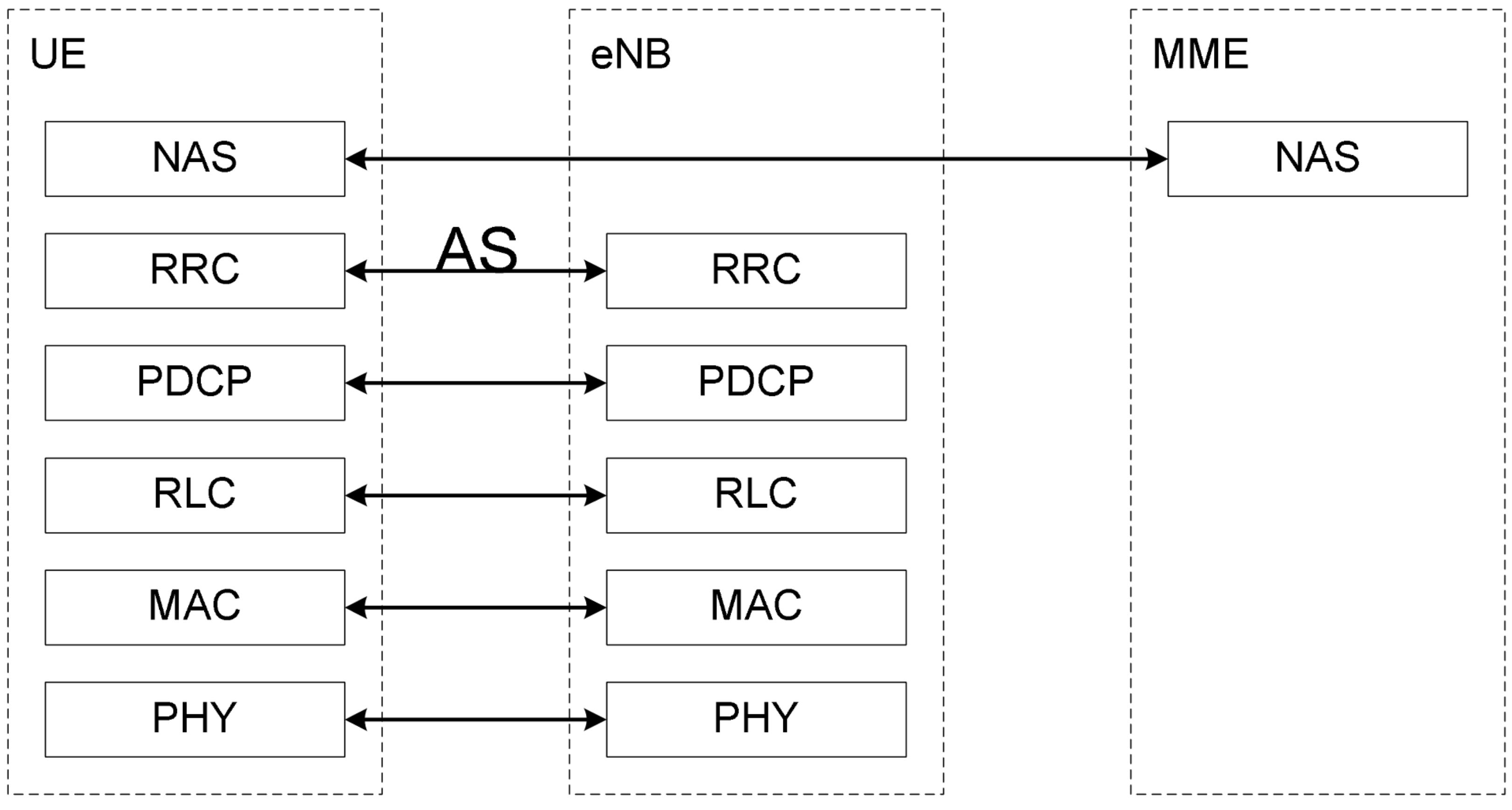
4G Control Plane Protocol Stack
In addition to the PHY, MAC, RLC and PDCP layer of the user data plane, the control plane protocol stack is extended by the Non Access Stratum (NAS) and Radio Resource Control (RRC) layer. Another good overview apart from 3GPP is this page.
“The Non-Access Stratum is a set of protocols in the Evolved Packet System” [Source]
Details can be found here.
Documentation about the RRC can found in 36.331 (Evolved Universal Terrestrial Radio Access (E-UTRA); Radio Resource Control (RRC); Protocol specification).
The RRC is already communicating in the Access Stratum (AS) and performs:
- Broadcast of System Information related to NAS and AS;
- Establishment, maintenance and release of RRC connection;
- Establishment, configuration, maintenance and release of Signalling and Data Radio Bearers (SRBs and DRBs);
- NAS direct message transfer between UE and NAS.
- Security functions
RDCP performs ciphering and integrity protection, while in general RLC, MAC and PHY perform the same functions as for the user plane:
- Radio Link Control (RLC) specified in 36.322
- Error Correction through Automatic Repeat Request (ARQ)
- (re)-Segmentation
- Concatenation of Service Data Units (SDUs) for the same radio bearer
- In-sequence delivery
- Media Access Control (MAC) specified in 36.321
- Multiplexing/demultiplexing of RLC Packet Data Units (PDUs)
- Scheduling Information reporting
- Error correction through Hybrid Automatic Repeat Request (HARQ)
- Logical Channel Prioritization
Connection Management
Connection and session management is handled between UE and the CN via NAS (24.301) protocol and between UE and E-UTRAN via RRC (36.331) protocols.
In general the NAS protocol (NAS) performs:
- authentication, registration, bearer context activation/deactivation and location registration management
In contrast, the AS protocol (RRC) performs:
- establishing connection, configuration the radio bearers, mobility control
Summary
We continued with the user and control plane, again starting at the protocol stack level and continuing with connection management. Signalling or control channel signify the same thing here: data to keep the system working. We learnt about bearers, the general structure of the control stack for user and control data and how scheduling is handled. Next time we will go deeper into the subject of control channels of LTE and then finally come slowly into the security corner.
Here you can read Part III and Part V.
See you soon. :)
Abbreviations
- Access Stratum (AS)
- Aggregate Maximum Bit Rate (AMBR)
- Allocation and Retention Policy (ARP)
- Automatic Repeat Request (ARQ)
- Core Network (CN)
- DownLink - Shared Channel (DL-SCH)
- Evolved Packet System (EPS)
- Evolved Universal Terrestrial Radio Access (E-UTRA)
- Guaranteed Bit Rate (GBR)
- Hybrid Automatic Repeat Request (HARQ)
- Long Term Evolution (LTE)
- Media Access Control (MAC)
- Non Access Stratum (NAS)
- Packet Data Convergence Protocol (RDCP)
- Packet Data Unit (PDU)
- Packet Data Units (PDUs)
- Physical Dedicated Control Channel (PDCCH)
- Physical layer (PHY)
- Prioritized Bit Rate (PBR)
- QoS Class Identifier (QCI)
- Radio Link Control (RLC)
- Radio Resource Control (RRC)
- Robust Header Compression (RoHC)
- Semi-Persistent Scheduling (SPS)
- Service Data Unit (SDU)
- Service Data Units (SDUs)
- Transmission Time Interval (TTI)
- UpLink - Shared Channel (UL-SCH)
- Voice over IP (VoIP)
Nils Mäurer
Group Head - Cybersecurity Architectures
My research interests include security of wireless communications systems, digital aeronautical communications systems, digital avionics and cybersecurity.